Entity Relationship Diagram as code means developers use the same tools for creating the diagrams – or documentation in general – as for coding.
Documentation includes more than just source code and some comments. If the documentation is textual and not binary, versioning can be easily done with continuous integration generating executable software and documentation.
PlantUML is a tool for creating UML (Unified Modeling Language) diagrams using a text editor. UML is a standardized modelling language that is commonly used in software engineering to design and document software systems. PlantUML can be used to automatically generate UML class diagrams, sequence diagrams, and other types of diagrams from source code, which can be helpful for understanding and analyzing the structure and behaviour of a software system.
It is also possible to create Entity Relationship Diagrams for database design. The PlantUML website contains an online server to make the first diagrams and offers to download a jar to make the diagrams locally.
The article will show examples of ER diagrams for Data Vault and Star schema with the source code.
Data Vault
Data Vault is a database design that is used in data warehousing for integration. It is designed to be flexible, scalable, and maintainable that can support the evolution of an organization’s data over time. Data Vault is particularly well-suited for handling large amounts of data, as well as data that is subject to frequent changes. The main entities are “Hub” (capturing natural keys), “Link” (capturing relationships) and “Sat(elite)” tables (capturing descriptions/context including history).
Below is a sample code and the corresponding diagram.

The code shows how to create entities using different colours. There are no checks or validations, e.g. for foreign keys. Markups like <<FK>> or <<unique>> are just for documentation. Primary keys are defined at the beginning before the line with two dashes “–“. Mandatory attributes are defined by “*”.
At the very end, the relationships are defined with cardinalities:
| Cardinality | Symbol |
| 0..1 | |o– |
| 1..1 | ||– |
| 0..n | }o– |
| 1..n | }|– |
For more syntax descriptions, see PlantUML ER diagrams.
@startuml
!theme cyborg
hide circle
skinparam linetype ortho

entity "H_customer" as hk01 #line:blue;back:lightblue {
  *c_id : binary
  --
  *customer_id : integer <<unique>>
  *loaddate : timestamp
  *recordsource : varchar(10)
}

entity "H_vehicle" as hf01 #line:blue;back:lightblue {
  *v_id : binary
  --
  *vin : char(17) <<unique>>
  *loaddate : timestamp
  *recordsource : varchar(10)
}

entity "L_owns" as lb01 #line:red;back:pink {
  *l_id : binary <<FK>>
  --
  *c_id : binary <<FK>>
  *v_id : binary <<FK>>
  *loaddate : timestamp
  *recordsource : varchar(10)
}

entity "S_customer" as sk01 #line:yellow;back:lightyellow {
  *c_id : binary
  *loaddate : timestamp
  --
  *recordsource : varchar(10)
  *firstname : varchar(200)
  *lastname : varchar(200)
  *title : varchar(20)
  *gender: varchar(20)
  birthdate date
}

entity "S_vehicle" as sf01 #line:yellow;back:lightyellow {
  *v_id : binary
  *loaddate : timestamp
  --
  *recordsource : varchar(10)
  *datebuilt : date
  *model : varchar(200)
}

hk01 ||..o{ lb01
hf01 ||..o{ lb01

hk01 ||..|{ sk01
hf01 ||..|{ sf01
@enduml
Star schema
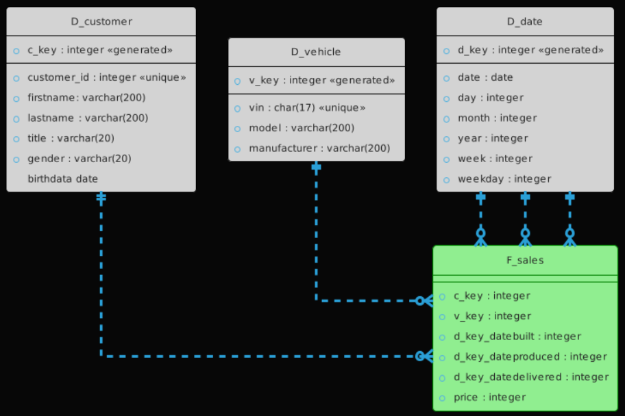
The star schema is a database design that is commonly used in data warehousing for easy querying of data. It is called a “star schema” because the diagram of the schema looks like a star, with a central table (the “fact table”) surrounded by several smaller tables (the “dimension tables”). The star schema is a simple and efficient design that allows for fast querying and analysis of large amounts of data.
Below is a sample code and the corresponding diagram.

@startuml
!theme cyborg
hide circle
skinparam linetype ortho

entity "D_customer" as dc01 #line:black;back:lightgrey {
  *c_key : integer <<generated>>
  --
  *customer_id : integer <<unique>>
  *firstname: varchar(200)
  *lastname : varchar(200)
  *title : varchar(20)
  *gender : varchar(20)
  birthdata date
}

entity "D_vehicle" as dv01 #line:black;back:lightgrey {
  *v_key : integer <<generated>>
  --
  *vin : char(17) <<unique>>
  *model : varchar(200)
  *manufacturer : varchar(200)
}

entity "D_date" as dd01 #line:black;back:lightgrey {
  *d_key : integer <<generated>>
  --
  *date : date
  *day : integer
  *month : integer
  *year : integer
  *week : integer
  *weekday : integer
}
entity "F_sales" as fm01 #line:green;back:lightgreen {
  --
  *c_key : integer
  *v_key : integer
  *d_key_datebuilt : integer
  *d_key_dateproduced : integer
  *d_key_datedelivered : integer
  *price : integer
}
dc01 ||..o{ fm01
dv01 ||..o{ fm01
dd01 ||..o{ fm01
dd01 ||..o{ fm01
dd01 ||..o{ fm01

@enduml
Pros and Cons
PlantUML is a tool that allows users to create diagrams using simple, human-readable text. Some pros of using PlantUML include:
- Easy to learn: PlantUML uses a simple, intuitive syntax that is easy to learn and use.
- Flexibility: PlantUML can be used to create a wide range of diagrams, including class diagrams, sequence diagrams, and activity diagrams.
- Compatibility: PlantUML can be used with a variety of tools and platforms, including Eclipse, Visual Studio, and GitHub.
- Collaboration: PlantUML diagrams can be easily shared and edited by multiple team members, making it a useful tool for collaboration.
Some potential cons of using PlantUML include:
- Limited capabilities: PlantUML is a simple tool that may not have all the features and capabilities of more complex diagramming tools.
- Complex diagrams may be difficult to create: While PlantUML is good for creating simple diagrams, it may become cumbersome to use for creating more complex diagrams with many elements.
- Limited formatting options: PlantUML does not offer many formatting options, so it may not be suitable for users who want to create highly polished diagrams.
- Limited support: PlantUML is not as widely used as some other diagramming tools, so there may be limited support and resources available for users who encounter problems or have questions.